Ciao Paolo,
Grazzie per la permessa di parlare in Inglese, Il mio Italiano e solamento abbastanza buono per fare turismo !
So, no I've not built that OPT, it is just how I would do it for me.
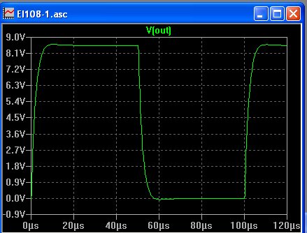
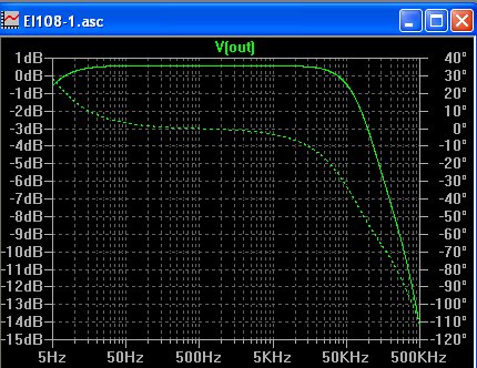
Of course, as long as it remains on paper, it is impossible for me to insure that results will be as expected but look at the attached simulation I reasonably trust in.
Note that there are no resonant frequency and that phase shifts gently at edge of band.
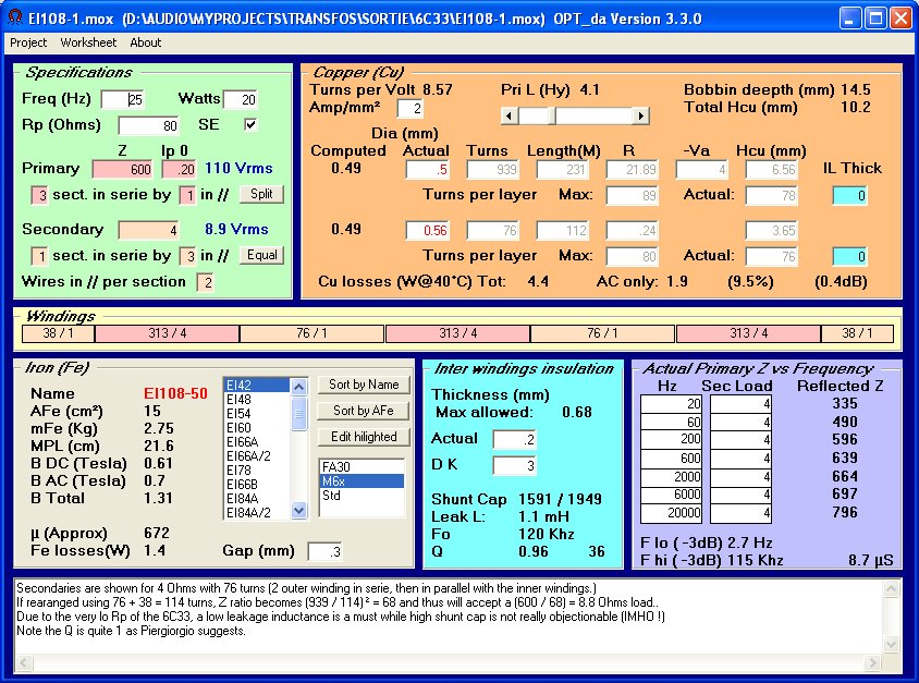
About the losses, 0,4dB means 10%, and vice et versa.
It also appears that, at 15W, induction remains less than 1,4T down to 20Hz.
A reduction of capacitance could be obtained in increasing the thickness of insulation beween primary and secondary sections, but this will increase leakage inductance and finally results in some in band resonances.
To bring back leakage down, we should use more sections, but this increase capacitance again and we will overflow from the copper window.
So, a larger iron should be used so that the turns number could be reduced, reducing in turn the leakage and increasing capacitance due to the larger areas face to face ! ! !
There is a point where miniscule improvements could only be acheived at a large expense of time, money and time vasting.
Probably, we could try to obtain much more impressive values / numbers, something "eccezionale" or, in my humble opinion, somewhat "overdesigned".
Anyway, from my point of view, any OPT is a sum of compromises and here is what I beleieve to be a very good one.
I've made a small improvment changing secondary wire dia and using wires in parallel.
This to optimize the filling of the copper window and reducing skin effect.
File updated, reload it if needed.
Ivo.